
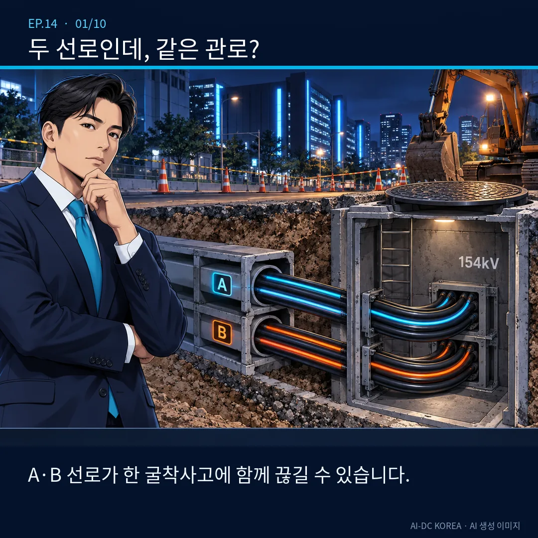
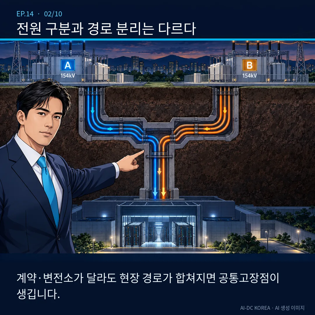
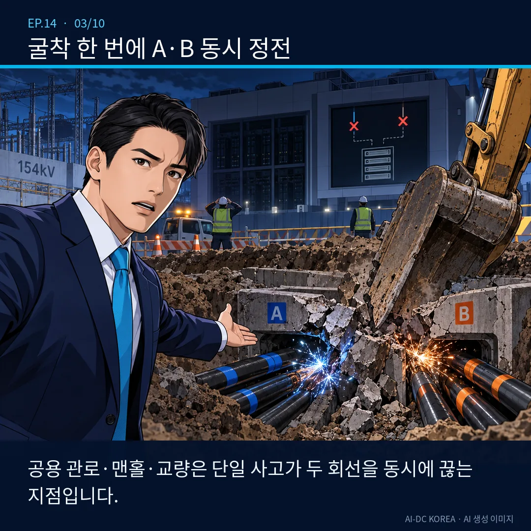
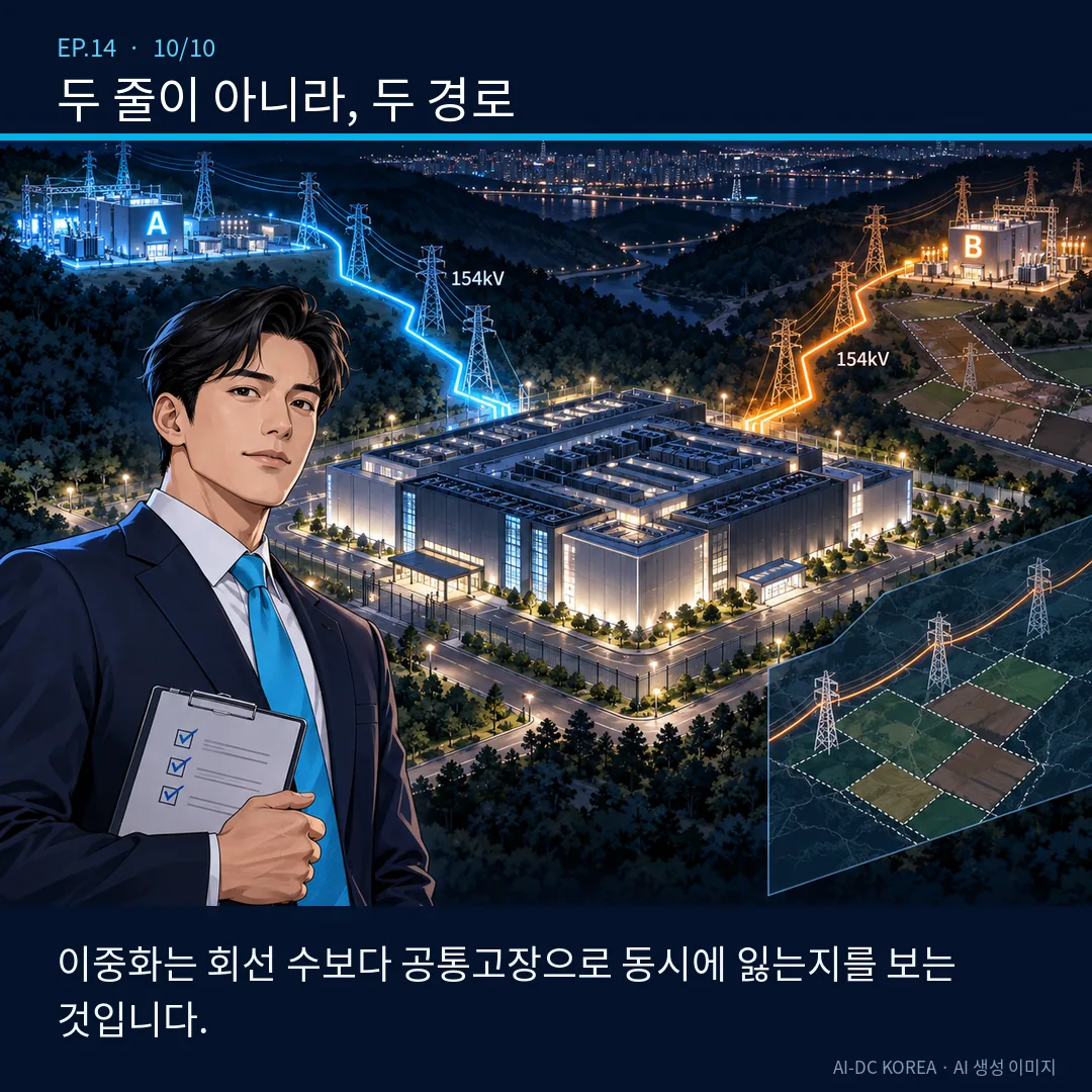
The term “two lines” alone is insufficient. Even if the sources and contracts differ, if they share common conduits, manholes, bridges, power distribution panels, and control power supplies, a single incident could result in the loss of both lines simultaneously.
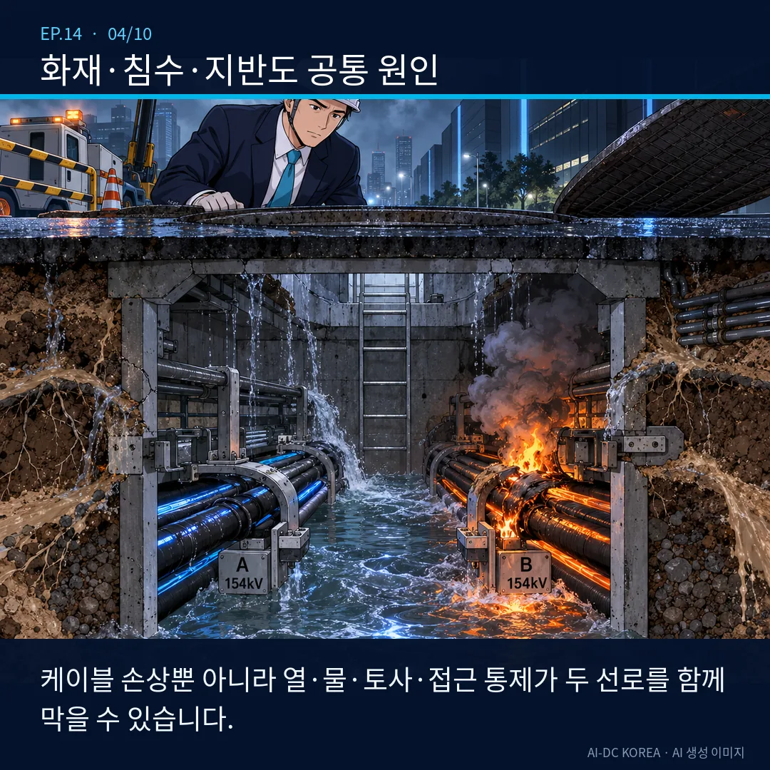
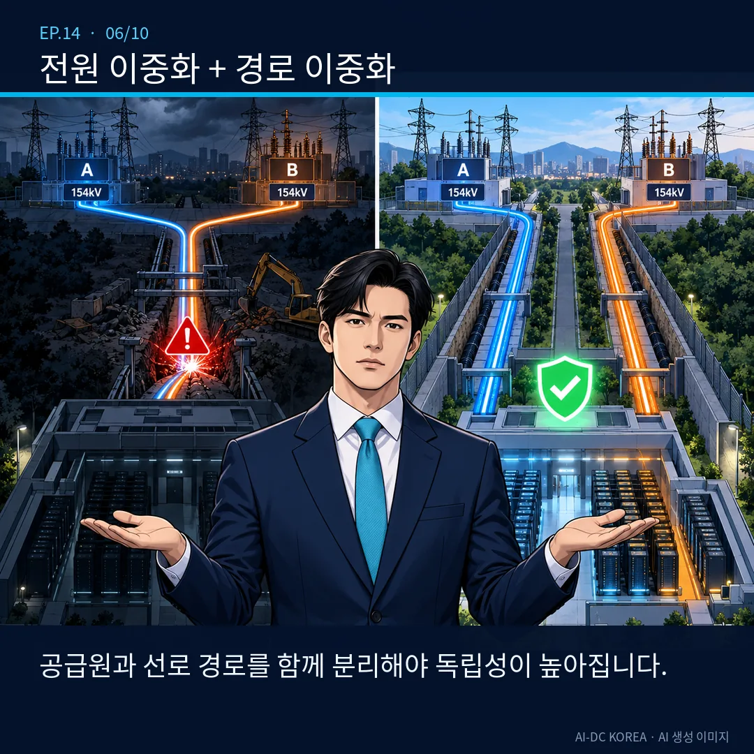
Even if 154 kV commercial power and reserve power are separate contract items or are supplied from different substations, if the actual power lines pass through the same power corridor, conduit, manhole, bridge, or tunnel, Common Point of Failure (CPF)This remains. This means that while the system can handle failures in the lines themselves, accidents affecting shared sections—such as excavation, fire, flooding, or ground collapse—could cause both lines to go down simultaneously.
In KEPCO’s Standard Supply Terms and Conditions, “Reserve Power (A)” and “Reserve Power (B)” are distinguished based on the supplying substation and voltage conditions. One should not assume, based on these designations alone, that the on-site power lines are physically separated. Contract and supply source distinctions, as well as path independence, must be verified through separate drawings and on-site surveys.
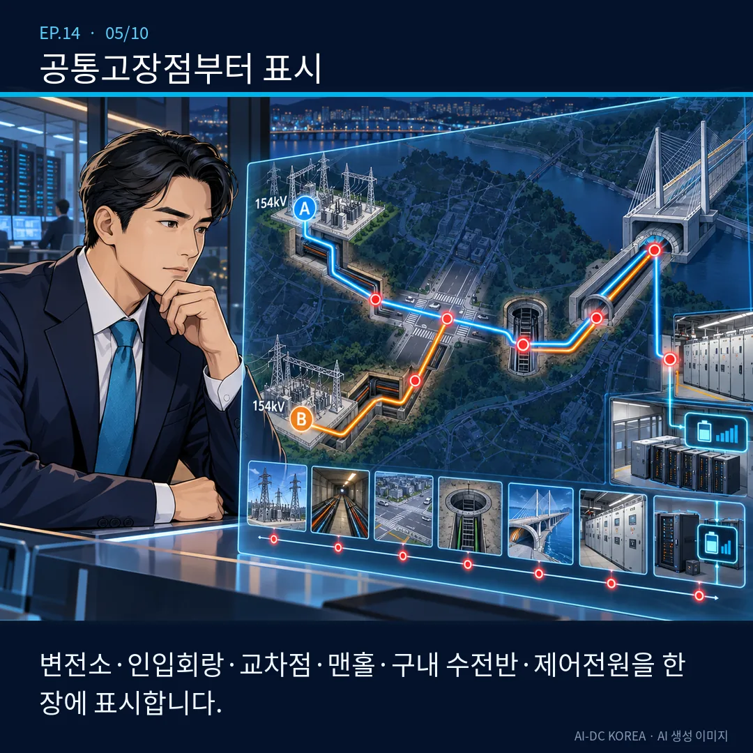
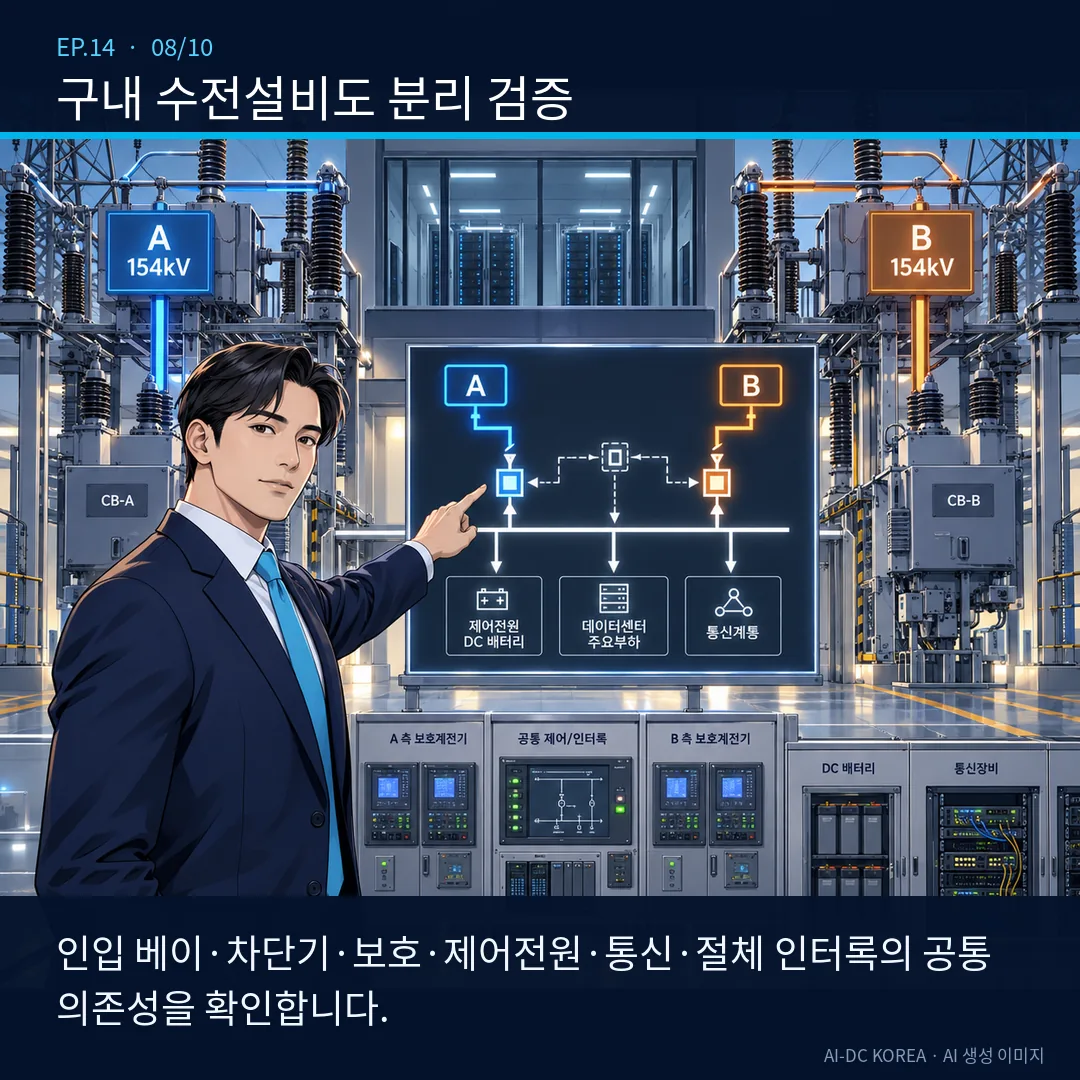
The list of common features does not end with substations. Feeder buses, transmission towers, underground connection points, road crossings, shared utility tunnels, manholes, bridges, on-site service corridors, power receiving bays, circuit breakers, protective relays, DC power supplies for control, communications, and switching interlocks are all shown on a single route diagram. We evaluate, by accident type, whether a single common point could lead to the simultaneous loss of both circuits.
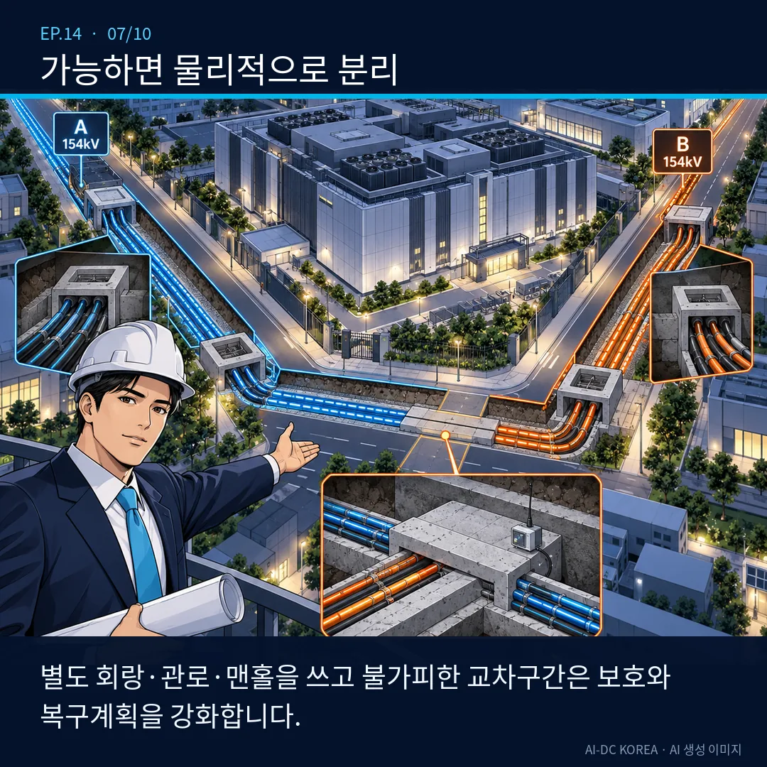
Whenever possible, configure the two circuits using separate corridors, ducts, and manholes, and connect them to different directions of the data center via separate entry bays. For unavoidable crossings or shared sections, strengthen structural protection, fire compartmentation, drainage and flood monitoring, excavation control, and ensure sufficient spare parts and recovery routes. Rather than arbitrarily applying a single separation distance value to all sites, designs should be tailored to the topography, voltage, cables, ownership sections, and accident scenarios.
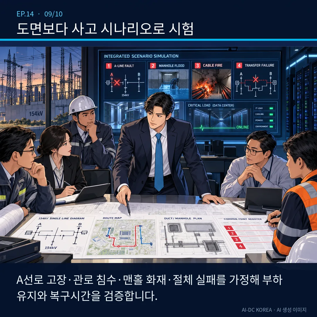
The final verification consists of drawing reviews and integrated testing. We simulate the following scenarios in sequence—Line A failure, Line B failure, flooding of a shared manhole, cable fire, loss of protective relays and communications, automatic disconnection failure, and re-disconnection after power restoration—to verify whether critical loads can be maintained using UPS systems and generators, as well as to determine the recovery time. The U.S. Department of Energy also explains that a site capable of receiving power from two independent substations enhances reliability.
Working-level submission materials: Review the 154 kV single-line diagram, the supply substation and actual transmission line route map, the plan view of conduits and manholes, the common point of failure register, the protection, control, and communication dependency table, the switching sequence, and the load maintenance and restoration test plans for each type of fault.
※ This content is intended for initial feasibility and site reviews. Actual supply routes, scope of construction, classification of reserve power, protection coordination, and separation and protection conditions must be finalized through KEPCO’s technical review, detailed design by a registered electrical design firm, and consultation with relevant agencies.
Start site analysis, including the 154 kV feeder route →